Cable sizing
Introduction – Cable sizing in PV systems[edit | edit source]
In designing a solar or electrical system, it is important to pay attention to the cable size selection as this is a critical part of the overall system. Properly selecting and sizing all the cables in a solar system is crucial to ensure adequate system performance and safety compliance.
Voltage, as an electrical quantity, plays and important role in electrical systems like solar systems. Hence, it is beneficial to avoid voltage drop in a system as much as possible. This can be achieved by selection of proper cables and conductors within the system. If an undersized cable is selected, this may lead to voltage drop that can affect system performance and compromise the safety as wires may heat up which may result in fire !
In cable size selection, a key electrical quantity that is considered is current. Electrical wires carry current much like a water hose carries water. For the water to flow properly with minimal resistance, a larger diameter of water hose is required. Also, the longer the hose, the more the diameter required to ensure resistance free flow of water. Electrical wires behave in the same manner.
In determining the smallest allowable cross-sectional area of a cable or circuit conductor, the following steps can be applied:
- Determine the full load current of the system or circuit
- Determine the method of installation for the cables
- Select appropriate size of conductor based on Current carrying capacity and method of installation
- Determine voltage drop based on selected conductor and cable length
- Ensure voltage drop follows applicable standards
- Confirm the cable short circuit capacity is higher than the system short circuit current. (not detailed in this article has almost every time OK in Distributed Generation applications, but to be carefully crosscheck for power plants)
Selection of cable type[edit | edit source]
Rated Voltage[edit | edit source]
It is necessary to select a power cable capable of supporting the system voltage. Generally, both phase and line voltage are indicated on the cable.
Copper or Aluminium cable selection[edit | edit source]
Copper and Aluminium are the two major types of conductors utilized in electrical and solar systems. Aluminium has 61 percent of the conductivity of copper but has only 30 percent of the weight of copper. Due to the high cost of Copper, Aluminium is usually the alternative option albeit requires a bigger cross-section area of conduction for a given current capacity compared to copper. Aluminum also offers lightweight and more cable flexibility that allows easy installation. In a solar system, both alternating current (AC) and direct current (DC) exist. These should be considered in cable selection for a solar system.
Usually:
- Copper is used for short distances, for PV cables (4 to 10mm2 cables), residential, commercial and industrial applications
- Aluminium is used for transport of high current over long distances (power plants, electricity transport)
Selection of Aluminium or Copper should be done based on the energy loss difference VS cost difference.
Determining cables cross-sectional area[edit | edit source]
Step 1 - Determine the full load current of the system or circuit[edit | edit source]
To calculate the full load current in Amps (A), you would need the full load power in Watt (W) and the voltage in volts (V). The formula to achieve this is: P=VI or I =P/V
Where P is the power in Watt, V is the voltage in Volt and I is the current in Amp.
For example, if the total load to be supplied is 4500W and the supply voltage is 220V, then the full load current can be calculated as:
4500 W / 220 V = 20.45 A
Note the following :
- For 3 phase systems, determine current on each phase and select highest current as basis for calculation.
- The full load can be calculated by simply adding the individual load in a circuit or system.
- The above formula for load current applies to both AC and DC circuits.
- For future or emergency needs, extra power can be added to the full load power. However, this depends where is located the cable in the system. For example, the output of a 20kVA inverter will never be more than 20kVA.
Step 2 – Determine the method of installation for the cables[edit | edit source]
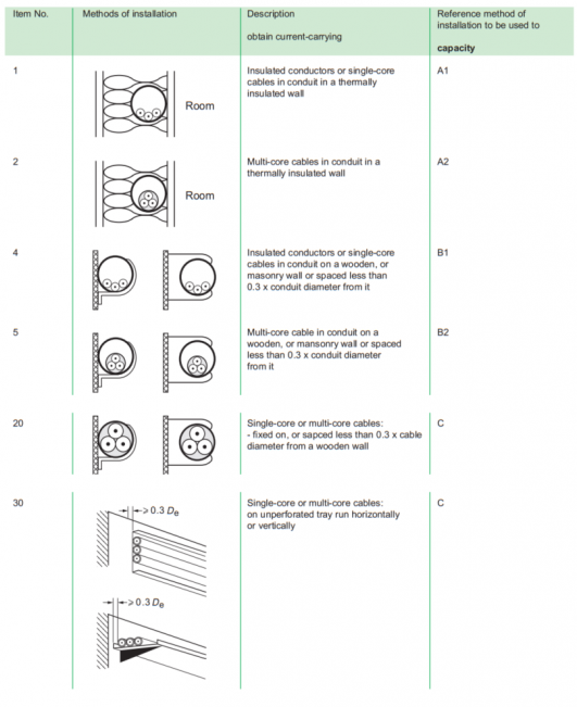
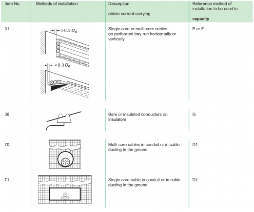
The ampacity of a conductor is the current carrying capacity which depends significantly on the method of installation and obviously the section. An illustration of some of the many different methods of installation is provided below. These methods are grouped with code letters A to G having the same characteristics relative to the current-carrying capacities of the circuit:
The above table is part of table A.52.3 of IEC 60364-5-52
Step 3 – Selecting appropriate conductor size[edit | edit source]
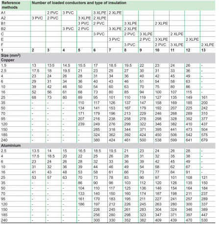
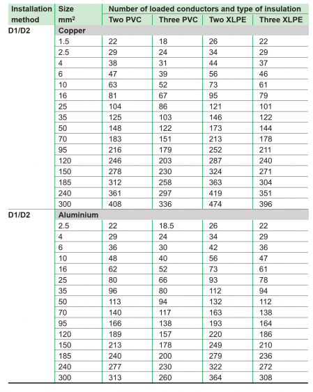
Selecting the conductor size for a circuit is based on the current carrying capacity and the installation method. IEC standard 60364-5-52 proposes extensive information in the form of tables giving the admissible currents as a function of cross-sectional area of cables.
Parameters considered in the table includes :
- method of installation
- type of insulation material
- type of conductor material
- number of loaded conductors
To facilitate the selection of cables, 2 simplified tables are proposed, for unburied and buried cables. These tables summarize the most commonly used configurations and give easier access to information.
Unburied cables[edit | edit source]
Buried cables[edit | edit source]
Following the example in step 1 with calculated current as 20.45 A, assuming the cable is to be unburied with 3 number of loaded PVC conductors, then the size of cable to be selected in 4mm2 which corresponds to 23A from the table above.
Step 4 – Determine the voltage drop[edit | edit source]
Maximum allowable voltage-drop vary from one country to another. Typical values for LV installation are given below:
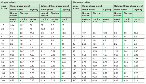
To avoid calculations, the table below can be used which gives the phase to phase voltage drop per KM of cable per ampere in terms of:
- Kind of circuit use: inductive or resistive with cos ϕ value of 0.35, 0.8 and 1
- Type of circuit: Single phase or three-phase
The voltage drop is then calculated from the table as :
K x IB x L
- K = Given by the table.
- IB = Full load current in Amps.
- L = Length of cable in km.
The column motor power “cos ϕ = 0.35” of the table below may be used to compute the voltage drop occurring during the start-up period of a motor.
Again, following the same example with 4mm2 cable selected, assuming the cable is to run for 30m (0.03km) connected to resistive load (cos ϕ = 1), then the voltage drop for copper can be calculated as:
10.3 x 20.45 x 0.03 = 6.32 V
6.32V/220V x 100 = 2.87% voltage drop
If this value exceeds the voltage drop limit in your country, then select the next bigger cable till the value drops to within the acceptable limits. For example, if the voltage drop limit is 2%, we then select 6mm2 and recalculate the voltage drop as:
6.8 x 20.45 x 0.03 = 4.17 V
4.17V/220V x 100 = 1.89% voltage drop
Therefore, the cable to be used for this circuit is 6mm2.
Tools[edit | edit source]
Software tools are available that can make cable sizing and selection easier. Most commonly used are :
- ETAP
- Cyme
- https://mycableengineering.com/
- Some excel spreasheets like :
MyCableEngineering is an online and easy tool which we recommend.
References[edit | edit source]
- Applicable Standards
- Electrical installation guide according to IEC international standards – Schneider Electric
- https://www.electrical-installation.org/enwiki/General_method_for_cable_sizing
- https://www.electricaltechnology.org/2013/10/how-to-determine-the-suitable-size-of-cable-for-electrical-wiring-installation-with-solved-examples-in-both-british-and-si-system.html
- https://electrical-engineering-portal.com/cable-selection-application
